GAGE BLOCK HEADER PAGE
GENERAL CATALOG
Interference Fringe Interpretation
1. This procedure covers the interpretation of interference fringe patterns generated by either an Optical Flat or a Flatness Interferometer for the purpose of measuring flatness.
2. Fringe lines can be thought of lines on a topographical map, but instead of elevation, they represent lines of equal distance between a reference surface such as an optical flat and the surface to be measured. If both surfaces are flat, the fringe pattern will be a series of straight lines. It is always assumed that the reference surface of the Optical Flat or Interferometer is flat.
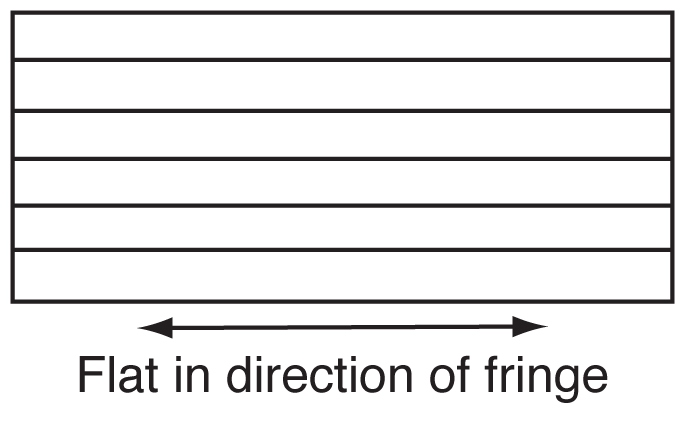
3. Any deviation of the reference surface from a perfect plane will be passed on as an error in the reading of the surface being read as it is assumed that the reference surface is perfectly flat.
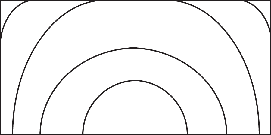
a. For any object, adjust the fringe pattern so that at least one fringe line goes from one edge to the opposite edge of the surface. This is used as the “measurement line.”
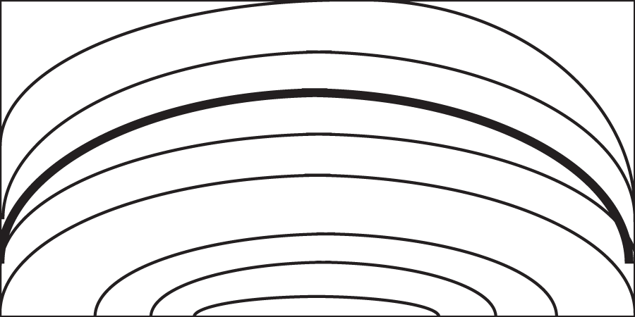
At least one line goes from edge to edge
No line goes from edge to edge
b. For small objects such as gage blocks or angle gage blocks, try to adjust the Optical Flat or Interferometer so that there are about three lines traversing the surface. (More lines are permissible, and even desirable if the surface being measured is not flat.)
c. For larger objects such an Optical Flats, it may be difficult to obtain such a few number of lines. For larger objects, try to adjust the viewing of the fringe pattern so that the lines are about 1/2 inch apart.
2. To measure the observed flatness, draw an imaginary straight line from the start of the “measuring line” at one edge to the end of the measuring line at the other edge.
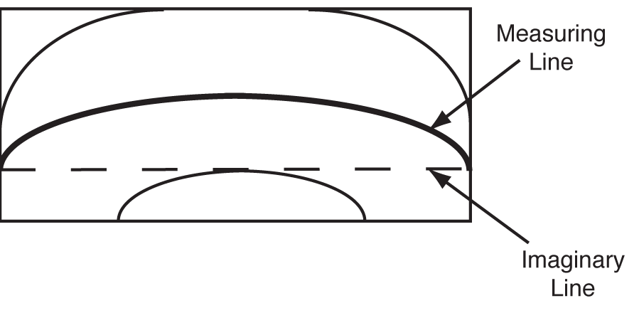
3. Count how may other fringe lines the imaginary line either crosses or touches. In the example above, the count is 1.
Other examples:
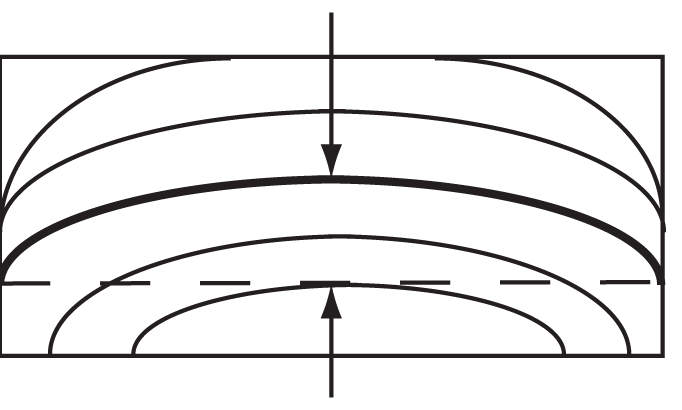
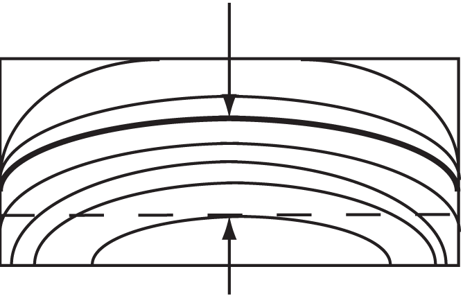
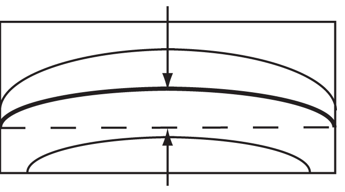
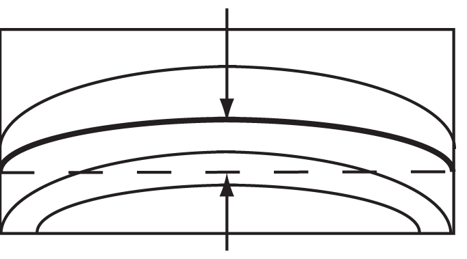
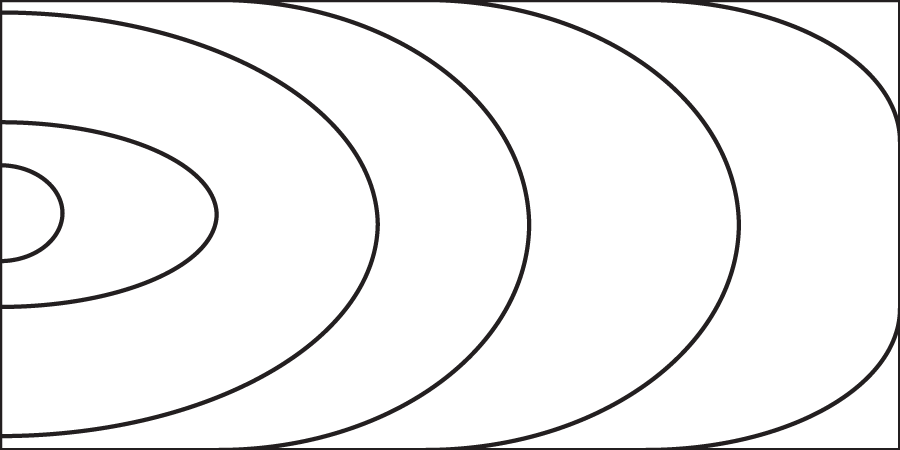
4. The pattern of fringes on a surface is to be viewed in at least two directions, 90° apart.
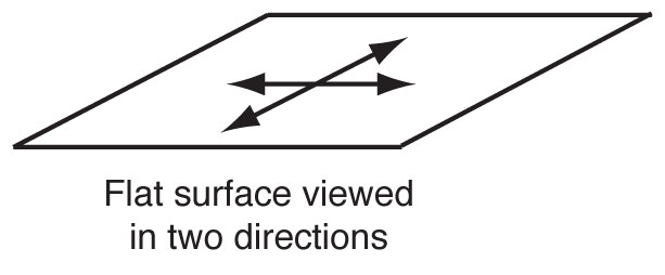
The measured flatness is the largest observed flatness. Finding the direction of maximum curvature of the fringes may require further adjustment of the Optical Flat or Interferometer.

5. Convert the flatness as measured in units of fringe lines to microinches (µin.). It is necessary to know the wavelength of light being used for the measurement. If possible, obtain the wavelength of the light source from the manufacturer of the lamp.
One Fringe Count or Band = One-half the wavelength of light used
Flatness (in µin.) = (Fringe Count)*(Wavelength of Light in µin.)/2
If the wavelength of the light is not exactly known, its wavelength may be estimated using the values below:
Green Light: Wave Length = 21.5 µin.
Red Light: Wave Length = 23.1 µin.
GAGE BLOCK HEADER PAGE
Fringe Pattern