|
 |
|
|
PREVIOUS
|
|
|
|
|
|
ANGLE GAGE BLOCK HEADER PAGE
|
|
|
|
Sources of Measurement Error for
Angle Gage Blocks and True Squares
|
|
|
1)  The error or uncertainty of measurement of the master angle block.
2)  The resolution or repeatability of the autocollimator setup.

3)  The flatness of the surfaces being viewed by the autocollimators.  This factor is a large
     contributor to measurement error and uncertainty.

     NOTE:  The type of autocollimator used in the measurement will have a great influence
     on the resulting measurement.   Different kinds of autocollimators may give different
     results.  How this is possible will be shown below.
|
|
|
|
 |
|
|
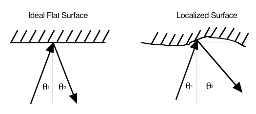
If the surface in not ideally flat, the angle of reflection may be different than the angle of
incidence.
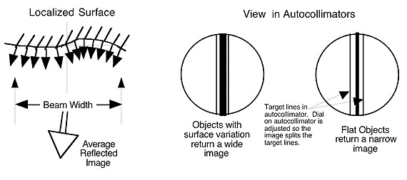
The autocollimators used by Webber Gage have a 2-inch diameter beam and are manually read.
The return image in visually centered between two target lines. The reading is taken off a
micrometer dial.
For reference and Calibration Grade blocks, the beam nearly covers the whole area of the block.
The angle indicated by the autocollimator is the average returned over the entire surface
of the angle block.
|
|
|
 |
|
|
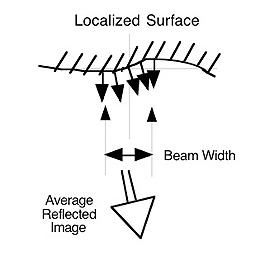
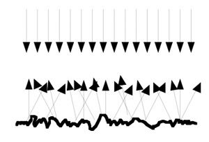
Autocollimators which have narrower beams such a laser autocollimators may give different
readings than autocollimators that cover the entire surface.
|
|
|
 |
|
|
The average reflected image in
this picture is different than the
average reflected image of the
picture above.
|
|
|
|
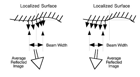
Positioning of the autocollimator may also effect the readings of an angle block.  This is another
effect due to flatness of the block. If the beam of the autocollimator is not centered on the angle
block, different readings may result.
|
|
|
|
 |
|
|
|
The measurement uncertainty factor (k=2) due to flatness is estimated to be given by:

         U = WF / (4.85 B)   where U is expressed in arc seconds and

        W = maximum dimension of the angle block (Width or Length) in inches,
                   or equal to B if W is smaller than B
        F =  measured flatness of the angle gage block surface in microinches
        B = Beam diameter of the autocollimator in inches.

       Note:  1 arc second is approximately 4.85 microinches of taper per inch.
|
|
|
|
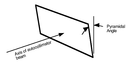
4)  Pyramidal Error.   The pyramidal angle is the deviation from 90°, forward or backwards, that the
     face of the angle block has to the beam of the autocollimator.   Ideally, the face of angle block
     is perpendicular to the vector represented by the centerline of the beam of the autocollimator.

     However, by itself, the Pyramidal Error does not have much effect on angle block
     measurements.   Measurement error is introduced when the autocollimator is not properly
     aligned to the axis formed by the side of the angle block.
|
|
|
|
 |
|
|
|
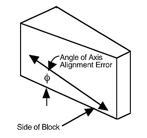
5)  Alignment of the axis of the autocollimator to the side of the angle block.  The autocollimator's
     axis of measurement must be aligned with the side of the angle block for proper measurement.
     If it is not, the autocollimator cannot measure the angle accurately.
|
|
|
|
 |
|
|
|
Measuring Error = P sin(ø) + a[1 - cos(ø)]   where

       P = Pyramidal Angle
       a = actual angle that should have been measured
       ø = angle of axis alignment error
|
|
|
|
6)  Surface finish.  For certain types of autocollimators, scratches on the gage surfaces may diffuse
     the reflected light and lead to erroneous readings.
|
|
|
|
 |
|
|
|
|
|
|
|
PREVIOUS
|
|
ANGLE GAGE BLOCK HEADER PAGE
|
|
|
AG31
|
|
©2018, Webber Gage Division, The L. S. Starrett Co, Westlake, Ohio , 44145
|
|
|
|
|
|
|
|
|
|
|
|
|
|
|
|
|
|
|
|
|
|
|
|
|
|
|
|
|
|
|
|
|
|
|
|
|